Anti-Cage Creep Linear Guides
Anti-cage creep (ACC) technology prevents cage drift in linear guides such as ball guides, cross roller guides, and needle roller guides. In more casual contexts, sometimes called anti-friction linear guides. Even with high accelerations of up to 15G and high-frequency short-stroke movements, ACC has been proven to be the most compact, robust, and reliable solution available in the market. Read here about our solution.
Home » Anti-Cage Creep Linear Guides
Introduction into anti-cage creep linear guides
Precision linear guides, often called cross roller bearings or caged linear guides, play a crucial role in various positioning systems. One set of linear guide consists of two pair of guides where one pair include two rails with a cage with rolling elements in between. However, the phenomenon known as “cage creep” can impact their performance. In this article, we’ll delve into the concept of cage creep, explore the need for anti-cage creep solutions, and highlight the unique features of PM’s Anti-Cage Creep (ACC) system.

The problem: cage creep in linear guides
Cage creep can occur in linear guides with limited strokes and cages. Typically non-recirculating linear guide applications where vibrations, improper mounting, very high acceleration (and de-acceleration), inadequate tolerances on the mounting surfaces, and uneven preloading, or moment loading are present. Vertical applications are also sensitive to cage slippage, simply due to the force of gravity where the cages slowly creep down.
What is cage creep?
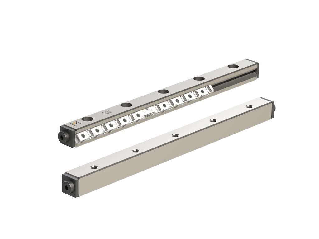
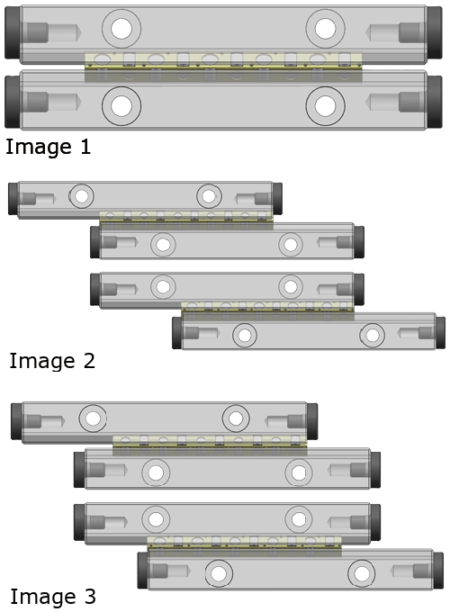
A linear guide consists of two guiderails and a cage fitted with rolling elements (balls, cylindrical rollers, or needle rollers). In this linear guide, the cage is positioned in the middle of the rail (image 1).
A linear guide has a certain maximum stroke. At this maximum stroke, the cage is just between the rails. It is held back by end screws or end plates (image 2).
A linear guide can be used in a system with, for example, high accelerations. During these high accelerations, the cage will slowly shift. This shifting is called creep. The result is that the stroke becomes smaller and smaller. As the cage drifts from its original position, increased friction, reduced travel length, and premature wear of the linear guides occur. By cage creep the cage will hit the end stops and can damage the cage (image 3). This results in a shorter lifetime and can result in premature failures of the linear guide.
Resetting the cage
To recover the maximum stroke, the cage has to be reset. For resetting, the end screw or plate at the end of the rail is used. During reset, the cage is pushed back to the middle of the rail using the end screw. If there is a lot of pre-tension on the set, a high force is needed for resetting. The force for the reset comes from the driving motor.
The term “Cage Creep” can be defined as follows:
Cage creep in linear guides is a undesired movement or slipping of the cage from its original position between the guide rails. This results in a shorter effective stroke length of the linear guide.
Factors contributing to cage creep in linear guides
The factors contributing to cage creep in linear guides include:
- High accelerations: Rapid accelerations can create forces that may cause the cage to slip from its original position.
- Influence of gravity during Z-movements: When the linear guide is involved in vertical (Z-axis) movements, the influence of gravity can contribute to cage creep.
- Misalignment: If the linear guide components are not properly aligned, it can lead to uneven forces on the cage, causing it to move unintentionally.
- Poor Adjustment of preload: Preload is the force applied to eliminate clearance between rolling elements. If the preload is not correctly adjusted, it can result in cage creep.
- Addressing and minimizing cage creep is crucial for maintaining the accuracy and reliability of linear guide systems.
Tips to prevent cage creep in linear guides
Cage creep can result in damage of the linear guides and unexpected downtime of the machine.
Here are some tips to prevent cage creep and ensuring optimal performance:
- Proper finishing of the mounting surfaces of the guide rails,
- Proper installation (link to installation guidelines of linear guides | step-by step),
- Good alignment of the rails, within the specified requirements (reference Installation guide)
- Precise adjustment of preload
- Correct lubrication and regular monitoring
When to consider an anti-cage creep solution?
When considering the need for an anti-cage creep solution in linear guides, several scenarios may hinder the conventional cage reset outlined in the preceding section. The following are situations where standard reset procedures may not be feasible:
- Insufficient cage strength: the cage in use may lack the necessary strength to resist pushing back to its standard position.
- Infeasible reset force: the required reset force may exceed the capabilities of the motor employed in the system.
- Space constraints in machine cycle: the machine’s cycle may not accommodate the necessary room or space for a reset stroke.
- Out-running cages: the presence of out-running cages can impede the straightforward resetting of the cage.
To address these challenges and enable the continued use of a set within a system, opting for a set with anti-cage creep (ACC) is recommended.
Applications of a set with ACC are particularly advantageous in vertical setups and high-acceleration environments. The absence of cage creep ensures reliability, making it an ideal solution in scenarios demanding high repeatability. The ACC feature guarantees that the rollers consistently return to the same position, maintaining the original adjustment at that specific location.
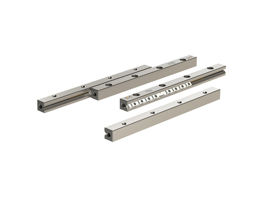
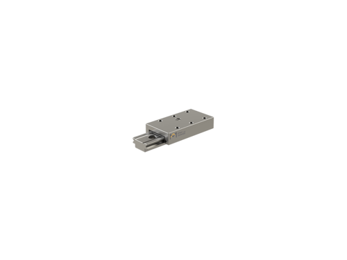
Linear guides with outrunning cages
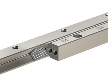
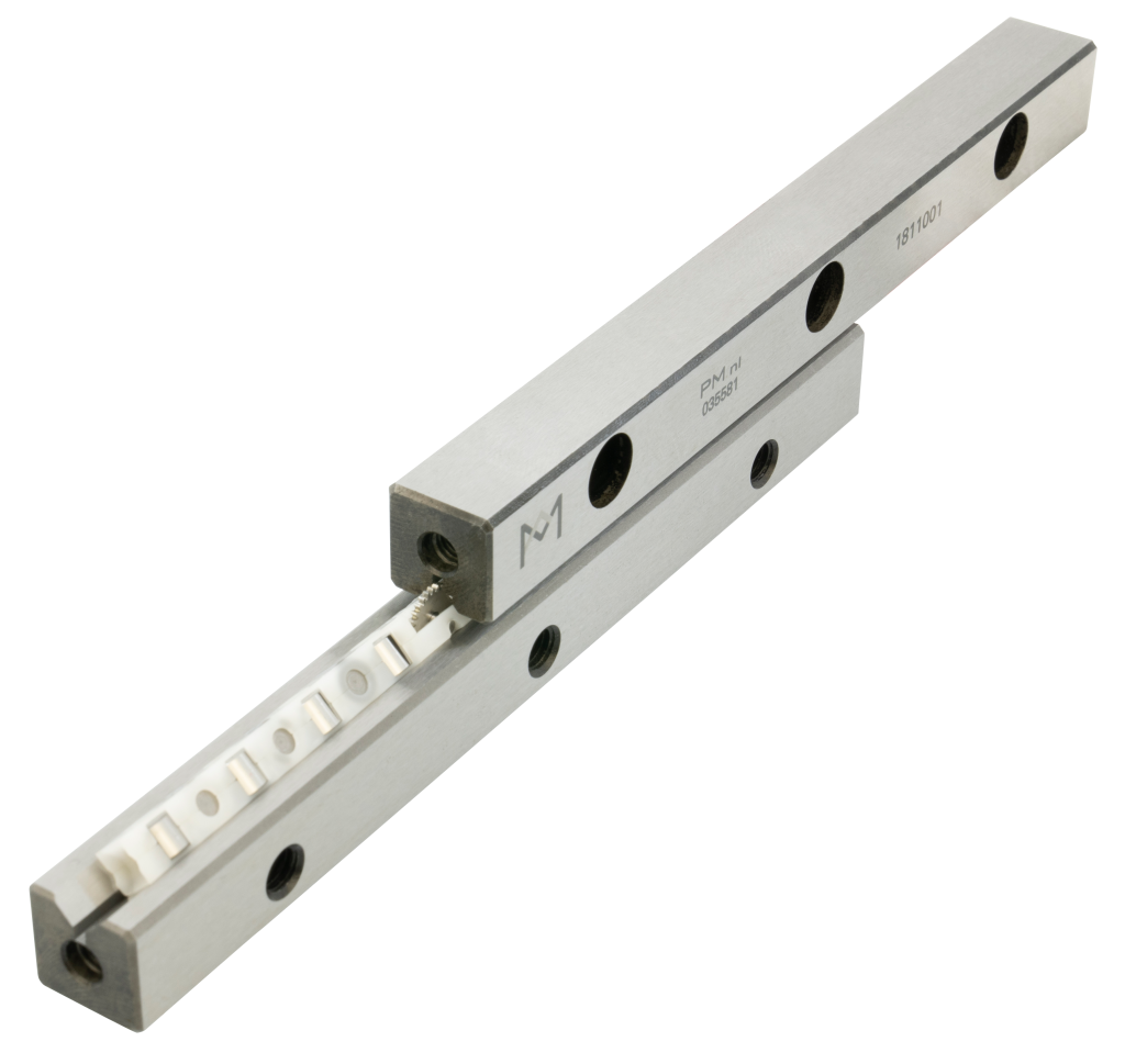
In situations were a shorter slide moves over a longer rail linear guides with outrunning cages are used. PM supplies linear guide sets where one of the two guiderails in a pair is shorter than the cage. As the cage is longer than the shorter rail these rail ends are without end pieces and supplied with rounded inlets. These inlets will help the cage to move-in or move-out of the pre-load zone of the rails more smoothly.
Not all cages are suitable for outrunning. It depends on cage characteristics such as cage material, cage length, and rail geometry. This all needs to be considered.
The advantage of outrunning linear bearings is that you need less installation space for the same stroke.
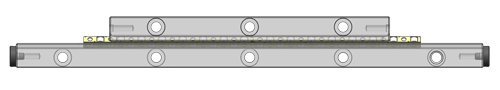

In the provided image, it’s evident that only one of the two rails extends beyond the cage. Despite using outrunning cages, there is a tendency for the cage to gradually shift over time. To perform a cage reset, the ability to exert force on the cage using both rails and the end screws is essential. However, the current setup lacks enclosure on one side, making a hard reset unfeasible.
Consequently, it’s not possible to reset a cage in a configuration where the cages protrude beyond the rails.
Introducing the anti-cage creep solution(s)
The concept of “Anti-Cage Creep” (ACC) refers to the technique of preventing any slipping of the cage that holds the rolling elements between the two V-groove rails of the slide way. By ensuring an accurate movement and eliminating creep creep, maintenance costs are reduced, precision is increased, and downtime is minimized.
PM engineers have further enhanced the anti-cage creep technology (ACC), making it suitable for high-tech and extremely dynamic applications. ACC is integrated into cross-roller linear guides either with a glued rack or Electro Chemical Machining (ECM) directly into the rail. Anti-cage creep is available in two versions:
- ACC: with glued rack from brass in the bottom of the V-groove
- ACCI: embedded rack machined in the bottom of the V-groove and through hardened. The length of the rail is limited by the machine. This version is only available with stainless steel linear guides. The (ACCI) anti-cage creep solution is popular with applications in vacuum and ultra-high vacuum environments.
For decades, the anti-cage creep solution of PM has proven its superior ability to prevent cage creep when applied in the most demanding applications and operating in the most challenging conditions.
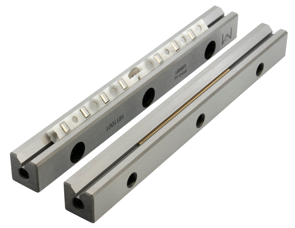
What makes PM’s ACC system unique
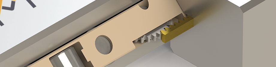
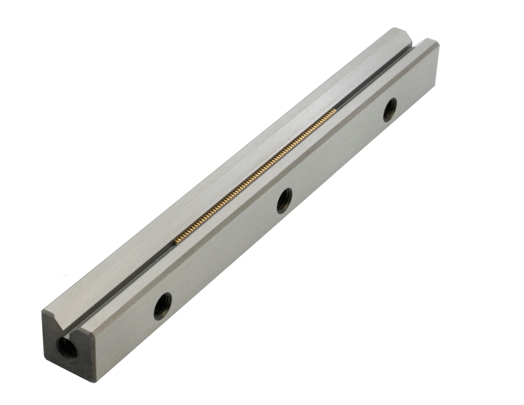
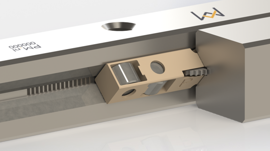
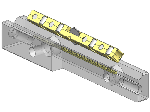
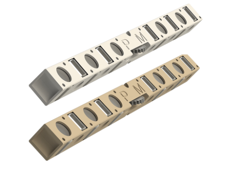
Within PM, an ACC based on a gear rack transmission according to DIN 867 is used. This gear rack is designed for continuous power transmission. The rack sits in the clearance (bottom of the V-groove) of the rail, the gear is part of the cage assembly.
The gear rack is placed internally in the set. The height and width of a set with ACC is the same as a set without ACC. The advantage is that this makes the sets interchangeable without adding extra costs for engineering and machining In case of failure, the sets can be easily swapped.
There are two versions of anti-creep systems within PM. In the standard type, a brass rack is glued into the bottom of the V-groove, this is called ACC.
Another solution is to integrate the rack into a stainless steel rail using ECM technology, this is called ACCI. The advantage of ACCI is that the rack is directly in the material, instead of having a glued connection which makes it more robust and suitable for applications in special environments as ultra-high vacuum.
Drop-in solution
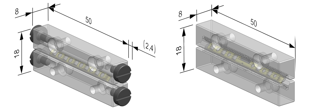
The ACC technology is integrated into the design of the linear guide without influencing the external boundary or mounting dimensions. Linear guides with anti-cage creep solution have the same attachment holes as the standard linear guides. This allows for drop-in replacement of guides in under-performing applications with the anti-cage creep solution without additional machining or redesign costs for table parts.
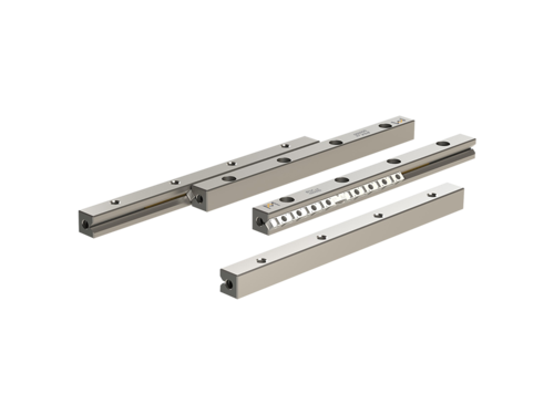
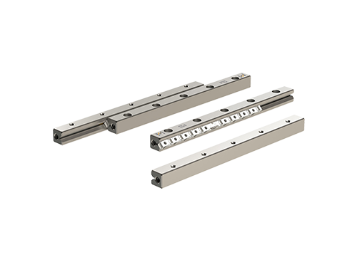
Type of linear bearings with anti-cage creep technology
We offer two types of linear bearing models which are available with anti-cage creep technology ACC;
- RSDE-ACC high load cross roller guide, available in roller sizes 3, 4, and 6 mm. Drop-in solution for the standard precision linear guides type RSD
- RNG-ACC, space and weight saving cross roller guide, available in roller sizes 4 and 6 mm.
The V-groove geometry offer for both rail types a longer surface contact area. In combination with the tightly spaced cylindrical rollers in the cage, the running features are unbeatable.
Materials used in anti-creep cages
There are two types of anti-cage creep cages in linear bearings. The cages can be used for both linear guide types, RSDE and RNG rail guides. For normal usage cage type, KRE can be selected, made of polymer (POM material) within the center a small metal spur gear that matches with the gear rack integrated into the rail.
For vacuum and ultra-high vacuum environments cage type KREV, made from PEEK is available in roller sizes 4 and 6 mm.
These roller cages can optionally be supplied with stainless steel cylindrical rollers.